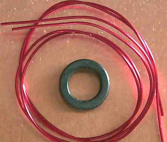

The trifilar wound transformer follows the same general idea but now you are connecting back both secondary wires. This is actually much easier to see in practice, than describe in words. The output of the transformer is the bottom end of the secondary. The "secondary" winding has its top end (same end of the wire as the PA B+ connection) connected back to the bottom end of the primary. The "primary" winding is connected between PA B+ and the Q1 MOSFET as usual. In the diagrams, the top end of the transformer in the diagram, is one end of the windings. When it came to the trifilar transformer, only measuring continuity with the DVM helps to identify which winding is which.Ĭonsider first the bifilar case.

I happened to have green wire and orange wire, which makes the bifilar transformer easy. It helps if you have different coloured enamel on the wires. The tricky part is keeping track of which wire is which. A trifilar transformer is similar, but now you twist together THREE pieces of wire.

You then wind this twisted wire 10 times through the core, to create a 10-turn bifilar transformer. You want perhaps something like 8-10 twists per inch (3-4 twists per centimetre), although it is not very critical. A "bifilar transformer" is made by taking two equal lengths of wire and twisting them together tightly. Bifilar and trifilar transformersĪ quick reminder. There is an even more dramatic increase in power if the PA bias voltage (R5 adjustment) is increased further. The bifilar transformer output significantly boosts the output power of the U3S, from typically 200mW to typically around 350mW. Some experiments on the U3S PA circuit were done, replacing the L1 25 turns FT37-43 with 10 turns Bifilar-wound and Trifilar-wound transformers.


 0 kommentar(er)
